Discovery Project
The Idea
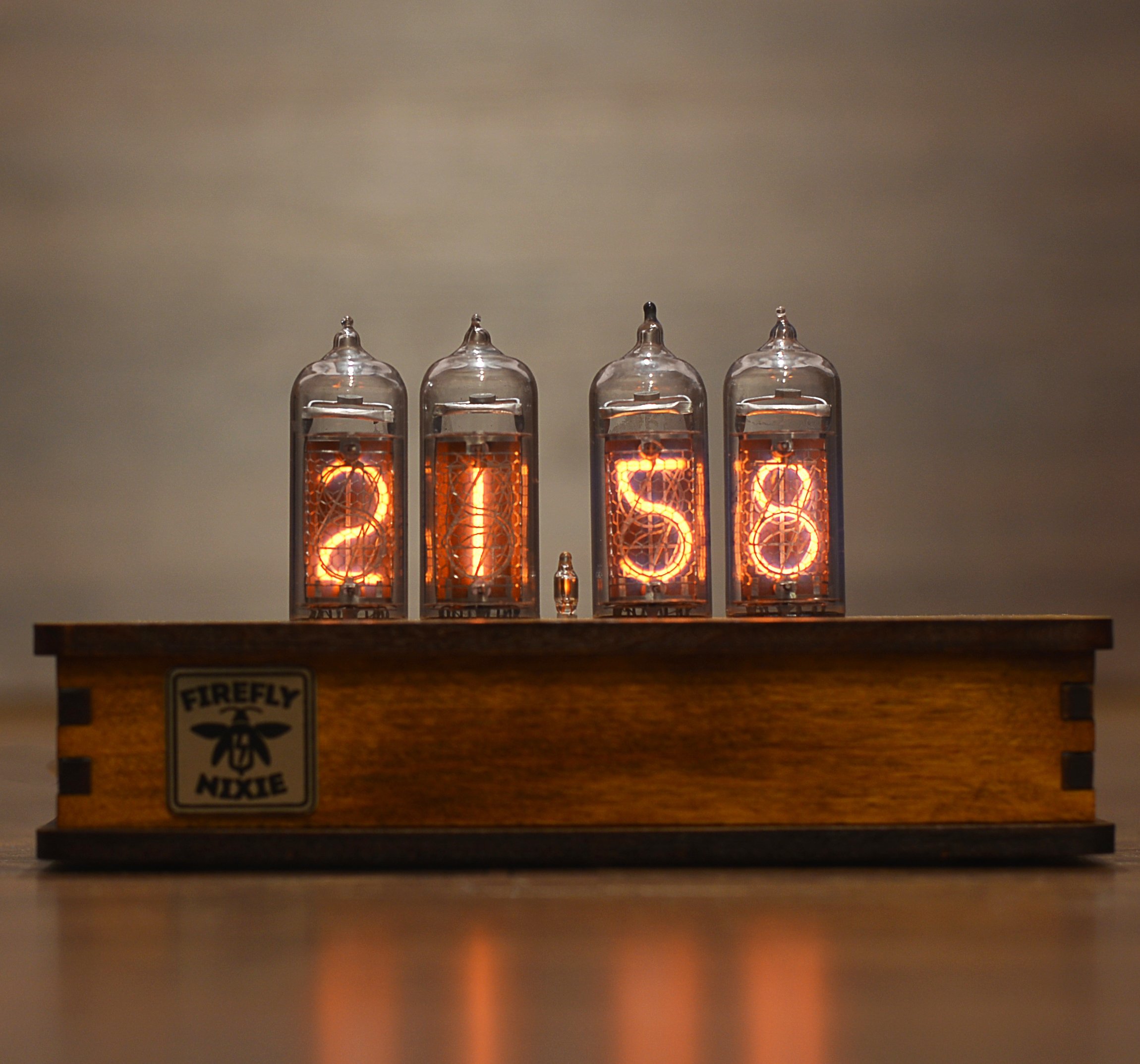
Nixie tube clocks, which were used throughout the 1950s, use glowing cathods to represent time. I found them to be really cool and loved their vintage look. However, it is really expensive to get the tubes now. They are also very dangerous as they operate at a really high voltage. Wanting to make a similar clock, I saw the alternative many people were going to, the Lixie.
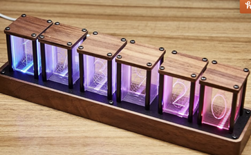
A digital clock that is inspired by old nixie-tube clocks. Each digit slot (4 digits) has 11 sheets of acrylic etched numbers 0-9 respectively, and a back sheet that is set to transparent or dark. The sheets each have 2 respective LEDs to diffuse light to display the correct combination of digits. This means 44 LEDS.
The image below shows a design I would like to replicate (but hours + minutes only).
https://www.tindie.com/products/lixielabs/lixie-ii-the-newnixie-for-arduino-digit-kit/
Skills and Tools Utilized
Skills I have utilized during this process include:
- PCB Design and Fabrication
- Microcontroller programming
- Basic 3D-printing & laser-cutting
- Soldering
My experience getting started
I needed to learn how to design a PCB. I watched some youtube tutorials and got assistance from some Peer Instructors at the Hive, the ECE MakerSpace.
To get some experience with laser cutting, I attended a laser cutting workshop at the HIVE. I designed and laser cut a wooden clock.
The Process
To start, I decided that I figure out how to design my PCB. To do so, I learned how to create a PCB using Altium Designer with help from peer instructors at the HIVE.
The PCB design should look similar to the product below:
https://www.tindie.com/products/lixielabs/lixie-ii-the-newnixie-for-arduino-digit-kit/
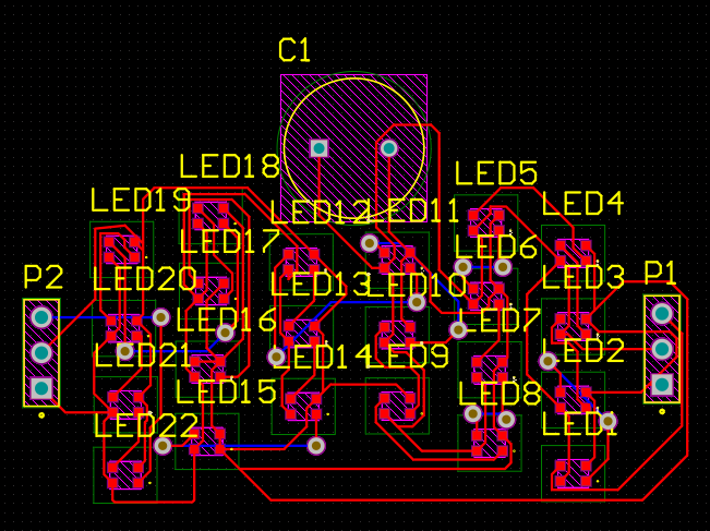
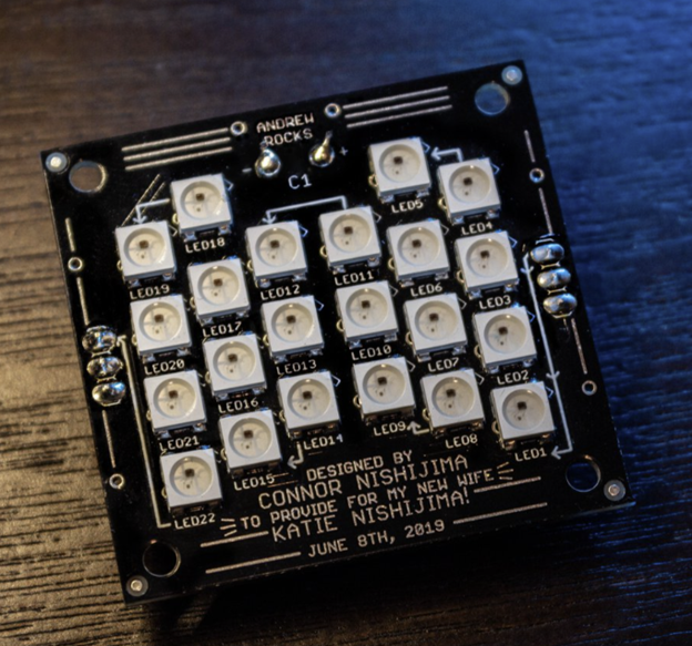
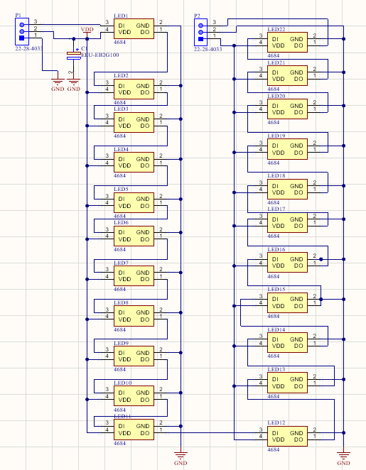
Here is the schematic I created for my PCB. The PCB schematic shows the 22 LEDs in series. There will be four of these PCBs daisy chained, meaning that 88 LEDs will be in series. However, this is not an issue as only 16 LEDs would ever be on at the same time (if the backlight is on, otherwise only 8).
My PCB layout will not have Vias. I decided to do this because the PCB printers at the HIVE are limited in their ability to do that. I plan to use the HIVE printers to learn how the machines function, and to have a prototype to mess with before ordering the real things. Here is a rough draft of the PCB board.